– by AUA and CETRI
The goal of WP4: “Implementation and testing of the solutions in pilot farms”, centres around the design, installation, testing, and monitoring of integrated energy systems at each of the four pilot farms. Following the designs, which were tailored to the needs of each farm, all Renewable Energy Sources (RES) systems were shipped, installed, and commissioned for each pilot farm.
- The experimental swine farm EV ILVO in Belgium (Photovoltaic-Thermal (PVT) collectors, heat pump)
- The commercial swine farm GOLINELLI in Italy (PVT collectors, heat pump coupled with ground heat storage)
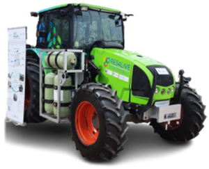
- The experimental dairy farm LVAT in Germany (PVT collectors, biomethane upgrading and fuelling a retrofitted tractor, e-tractor)
- The experimental poultry farm AUA in Greece (Photovoltaic (PV) collectors, heat pump)
The integrated systems are an optimal combination of adapted RES of WP1 (“Adaptation of innovative RES technologies for livestock farms”), with commercial solutions, finely tuned by the smart control system to meet the farms’ needs.
EV ILVO farm “VARKENSCAMPUS”
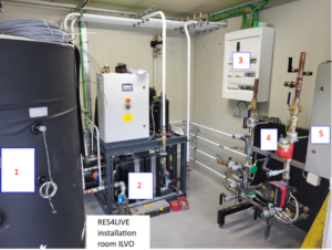
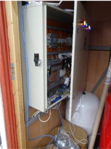
In EV ILVO, an existing meeting room has been converted into a RES technical room. As shown in the following picture, the buffer tank (1), the multi-source heat pump (2), and the solar station unit (4) with its electrical cabinet (5) have been installed inside the room. The main electrical cabinet (3) supplies all the above, as well as other equipment in the installation room, while it also connects the inverter to the grid. Outside the room, corresponding installations for the dry cooler with its hot and cold lines dry cooler and the power supply have been conducted. This is also the location of the installations for the hot and cold lines from the PVTs and the solar inverter.
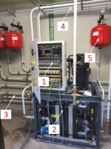
The modular heat pump installed and commissioned at EV ILVO, with the respective piping and control system (Figure 2), consists of the electrical panel and control system (1), and the main heat pump components (2) (e.g., compressor, heat exchangers, etc.). The pipe connections to and from the heat pump and the buffer tank (3), the return and supply connections to the existing technical room at (4), and the three expansion tanks on the heat pump circuit (5) are also shown in Figure 2.
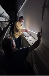
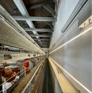
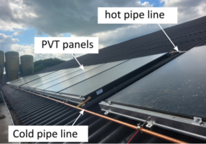
The PVT panels (shown in Figure 3) were installed in four groups, with each group consisting of 6 PVT panels. The heat transfer fluid circulates through the hot and cold pipelines. The fluid’s flow is controlled by the solar station unit based on the temperature of the working fluid and the solar radiation. The PVT system is in full operation delivering heat to the buffer tank and MG is monitoring its operation closely.
GOLINELLI farm
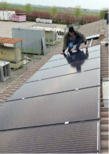
 The PVT system at GOLINELLI farm, installed on the roof of the nursery barn (B.16), consists of a set of 24 uninsulated PVT collectors, an inverter with cabling, and a solar station. The circulation of the fluid (water and propylene glycol) among PVT, BTES (Borehole Thermal Energy Storage), and dual-source heat pump (DSHP) (Figure 4) is controlled by the solar station and its controller developed and installed by MG Sustainable Engineering AB. The solar system was installed and commissioned in April and is in full operation delivering heat to the BTES. MG and UNIBO are monitoring the data closely.
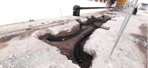
The designed BTES is composed of two circuits and four lines. All BHEs (Borehole Heat Exchanger) are involved, since in each BHE the double-U is divided between heat pump (HP) and solar station (PVT) lines. The entire set of connections is as follows:
| – Circuit 1: Heat Pump (HP) – BTES
o Line 1: from HP to BTES o Line 2: from BTES to HP |
– Circuit 2: Solar station (PVT) – BTES
o Line 3: from PVT to BTES o Line 4: from BTES to PVT |
The final connections of the two circuits were decided according to available space optimization of resources.
After verifying the correct hydraulic tightness of all pipes in the solar and geothermal circuits, the effective capacity of the heat pump (Figure 6) to heat the fined coils of the building was tested. The heat pump can switch from air to ground (activating and deactivating the fans), by rapidly responding to the set temperature threshold. The selection between ground and air is based on the comparison between the geothermal fluid return temperature and the temperature thresholds decided by the user.
Different on-field tests also proved the proper operation of the heat pump, for different geothermal circuit fluid temperatures and setpoints.
The main intervention in B.12, a hog barn without insulation as shown in Figure 7, is a retrofit of the building envelope by the replacement of the previous windows with a new opening system, equipped with an automation opening system suitable to minimize heat loss with proper air exchange. The new windows (Figure 7) are composed of a perimeter frame in tubular stainless steel and a frame and upper counter-frame in stainless steel, with a transparent double alveolar polycarbonate chamber infill. The automation system is made of six-gear motors with a limit switch for the mechanical opening, environmental sensors, and actuators driven by temperature and air quality parameters.


Figure 7: Detail of the new windows (left) – The building with the new windows installation (right).
LVAT farm
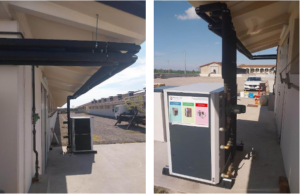
The already existing biogas plant at LVAT has been connected to the new filling station, where the biogas is then transformed into biomethane in a membrane filter system. This increases the biomethane concentration and as such produces BioCNG (with a methane share of >95 % on-farm), while the remaining gas components are led back into the biogas plant. The BioCNG plant can produce 5 Nm³ CNG per hour and will be used to replace diesel in a tractor which has been adjusted to run on gas instead of diesel (Figure 9). The filling process with the converted tractor takes about five minutes. The components of the installation of the CNG filling station plant are shown in Figure 8 (left), along with the CNG filling station and the biogas plant in the background.
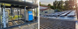
The PVT collectors were mounted on the roof of the LVAT’s larger dairy cow barn (Figure 8, right). Due to being an innovative collector, a bespoke roof mounting system was designed specifically for this installation by MG. The collectors, microinverters, and solar station were installed in May 2023. The hot and cold pipes from the solar field to the solar station, as well as the sensor cables, and part of the commissioning was completed in September 2023. The connections of the PV modules to the farm and grid, and the connection of the solar station to the milking tank heat recovery system still need to be completed by LVAT. Twenty of the 24 modules are equipped with two layers of photovoltaic cells on the top and the bottom for increased efficiency with a total aperture area of 45 m² and a presumed peak power of about 5 kW in total, while the remaining four modules are pure thermal modules. The PVT collectors contain fluid for thermal usage that is connected to a 1500L heat storage with a piping system to the farm.
The heat storage is located in the solar house (Figure 10), which is integrated with the heat recovery system in milk cooling improving its overall efficiency. Together these systems provide hot water for the barns in a temperature range between 50°C and 70°C that will be used in all domestic hot water needs of the farm, milking parlor, and during the cleaning operations.


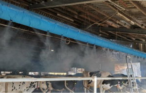
In LVAT’s welfare barn, the existing tube ventilation system was enhanced to provide the option to mix in pre-cooled air. The injection of cooled air in the welfare barn above the lying cubicles (Figure 11) and the feeding table provides additional comfort for the cows during days with higher temperatures and consequently higher risk for heat stress. Depending on ambient conditions, the ventilation system allows to drop in the temperature in the welfare barn by 5 to 10 K.
Agricultural University of Athens farm
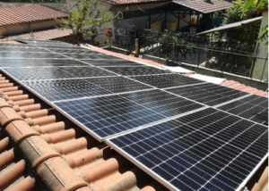
The selected 9 kWp PV system was installed on the rooftop of a nearby building, north of the experimental poultry house, marked as in Figure 12, with a south orientation. The PV system is designed to cover the poultry house energy needs on a yearly basis, considering the location and available space. No storage system has been included, so when the PV production cannot meet the facility’s needs, the power comes from the grid. In case of excess power, the nearby auxiliary buildings are supplied.

For enhancing the thermal comfort of hens and broilers, a heat pump of PSYCTO with a capacity of 10 kW has been installed. To this end, it is capable of operating in heating, cooling, and dehumidifying modes. The overall heat pump system’s arrangement for regulating the indoor environment (i.e., keeping the temperature and humidity within the thermal comfort zone) is shown in Figure 13.
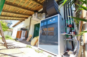
The hydraulic connections were installed, starting with the connection of the dry cooler to the heat pump. Next to the exhaust fan, a recuperator for waste heat recovery from the air coming out of the poultry house was installed and connected to the heat pump.
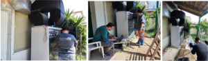
Finally, electrical connections and commissioning of the integrated systems took place. The above-mentioned heat pump components are shown in Figure 14.
The LED installation has been completed, and the final programming took place in early January 2023 (Figure 15). The LED strips’ drivers are powered by a subpanel and they are controlled by a fully programmable control unit. The system is fully operational programmed and/or manually controlled by the web and mobile application of the manufacturer.